This is an HF circuit note for my personal blog, and it's my effort to understand this circuit. The idea is, if I blog about it, I may just come to understand it. This mixer is an example of a circuit that enables superheterodyne and direct-conversion receivers and forms part of the SolderSmoke Direct Conversion Receiver Challenge. The interactive companion at the top is designed to demonstrate the principles involved; the sections below explain how the four-diode ring does the job. The commutation picture follows Experimental Methods in RF Design (EMRFD), Figs 5.19–5.20. Shamelessly ripped, but sometimes you can't do better than the original.
1. What a mixer actually does
A frequency mixer is a three-port device with two inputs and one output:
- RF — the signal you want to translate in frequency - ultimately demodulate (often an antenna after some band-pass filtering and maybe amplification).
- LO — the local oscillator, a strong, stable tone generated locally. Usually sweepable, so we can tune in a range of frequencies in the RF band.
- IF — the intermediate frequency output where the translated signal appears.
In an ideal case, the IF contains only the mixing products of RF and LO, not the originals. For sinusoidal inputs at frequencies $f_\text{RF}$ and $f_\text{LO}$, the product has components at
(the sum and difference). In a downconverter, such as the SolderSmoke Direct Conversion Receiver, we keep the difference $|f_\text{LO} - f_\text{RF}|$ and filter out the sum and the input frequencies. In the specific case of a direct receiver, we generate our LO so close to the actual RF of interest that the difference lies in the Audio Frequency (AF) region, which we can hear directly.
The whole trick is to make the LO and RF multiply in a mathematical sense, which will generate both sum and difference frequencies. To see why, we will need to do some maths.
2. Multiplication in time, addition/subtraction in frequency
If both ports are pure cosines,
then the instantaneous product contains (among other terms)
The sum $f_\text{LO}+f_\text{RF}$ and difference $|f_\text{LO}-f_\text{RF}|$ are exactly the two IF products we care about. Tab 1 — Mixing Fundamentals of the simulator plots this directly: two input tones, one product trace, and an FFT showing the two new lines.
Real diode mixers do not multiply perfectly, especially in a mathematical sense, so how can we achieve something like multiplication? Well, by applying an alternating voltage (LO) that switches the diodes on/off, we can effectively switch the RF from positive to negative at the applied LO rate. Basically, multiplication by a square wave at $f_\text{LO}$. That is, this switching is equivalent to multiplying the RF by either +1 or -1 at the LO rate. This is the necessary **multiplication** of the equations above to generate the required mix, yielding $f_\text{IF} = f_\text{LO} \pm f_\text{RF}$. In short, the multiplication is not by a sine wave because this is not electrically possible; instead, it is by a square wave. Because switching polarity is the Fourier series of a square wave, which contains odd harmonics of $f_\text{LO}$, real IF ports also show spurious responses at $|k f_\text{LO} \pm f_\text{RF}|$ for odd $k$. A balanced topology cancels many of those, which is why we use the four-diode ring. Simpler mixes are easier to build but suppress less, and we won't discuss them here. Instead, let's try to understand now how the four-diode balanced ring suppresses unwanted harmonics.
3. The four-diode double-balanced ring
The classic double-balanced diode ring mixer uses four diodes in a square ring, with RF and LO each fed through a balun (balanced-to-unbalanced transformer) so both appear as differential signals across the ring:
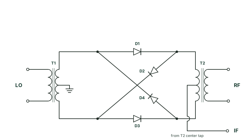
This circuit is basically that laid out in Experimental Methods in RF Design Fig 5.19 panel D.
The key ideas:
- LO switches the ring. During each half-cycle of the LO, one pair of diodes conducts while the other pair is off. The RF path is alternately connected with normal and inverted polarity.
- Balanced inputs suppress feedthrough. Because both LO and RF enter differentially, neither tone should appear at the IF port in the ideal case — only the products. Layout symmetry, diode matching, and balun quality determine how close you get in practice. You can spend a considerable amount of time tuning all this, but don't let the perfect be the enemy of good enough here.
- The IF is picked off through a low-pass or band-pass network that blocks RF and LO but passes the difference (and whatever sum you have not filtered out). In our case, we low-pass audio.
Commutation: the ring as a polarity switch
It is worth slowing down on point 1, because the switching picture is so critical. Trace the two LO half-cycles separately:
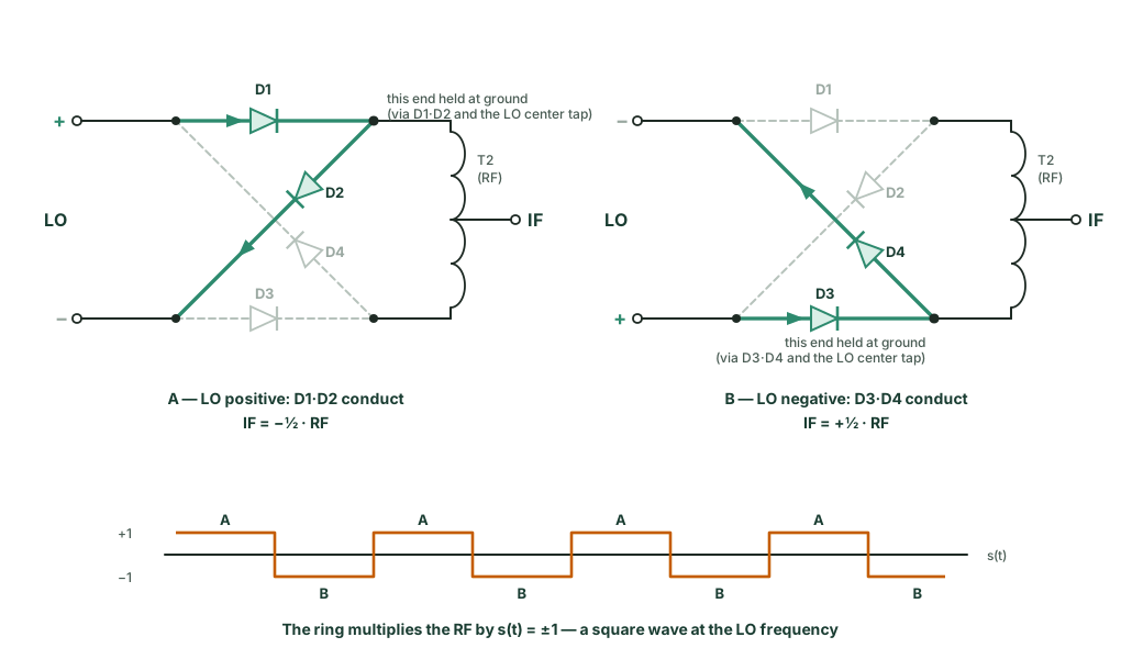
Two things fall out of this picture immediately:
- The LO does no more than commute polarity. The IF waveform is the RF signal with its sign flipped at the LO rate — the LO's own amplitude and waveshape (past "enough to switch the diodes hard") do not appear at the IF. This is why diode mixers are so tolerant of LO harmonics - they don't (ideally) appear at the IF port. None of the LO appears there.
- The multiplication model is exact for an ideal ring. Multiplying by $s(t)=\pm1$, whose Fourier series is $\frac{4}{\pi}\left[\sin\omega_\text{LO}t + \tfrac13\sin 3\omega_\text{LO}t + \tfrac15\sin 5\omega_\text{LO}t + \cdots\right]$, produces products at $|k f_\text{LO} \pm f_\text{RF}|$ for odd $k$, with amplitudes falling as $1/k$. The even harmonics are absent by symmetry — that is, the "double balance" is doing its job. The fundamental term gives the familiar sum and difference at $f_\text{LO} \pm f_\text{RF}$.
4. Superheterodyne: LO far from RF
In a traditional HF receiver, the LO sits near the RF but offset by a fixed IF — classically 455 kHz in many AM broadcast designs, or a few megahertz in shortwave gear.
Example: RF = 10.455 MHz, LO = 10.000 MHz → IF = 455 kHz.
The RF of interest might be at 10.455 MHz; the LO runs at 10.000 MHz, and the IF strip — filters, gain, demodulator — is built entirely at 455 kHz, where stable filters and plenty of gain are easy to achieve. You have moved the information riding on the RF carrier down to a convenient, fixed frequency without changing anything else.
Tab 2 — Superheterodyne (455 kHz IF) in the simulator walks through this case with the same numbers scaled for display. Notice how far apart the LO and RF peaks are in the spectrum, and how a single strong difference line appears at 455 kHz while the sum sits near 20.9 MHz - this is easy to filter away.
5. Direct conversion: LO close to RF
In a direct-conversion (zero-IF or homodyne) receiver, the LO is right on top of the RF — or offset by at most a few kilohertz. The difference frequency lands in the baseband: DC to a few tens of kilohertz, often straight into an audio chain designed to amplify audio and supress higher frequencies that may have slipped through the mixer.
Example: LO = 7.100000 MHz, RF = 7.101000 MHz → IF = 1 kHz (inside the audio band).
That is the same multiplication physics as the superhet, but now $|f_\text{LO}-f_\text{RF}|$ is so small that the difference product is an audio tone. One subtlety worth being precise about: the slow 1 kHz sine only emerges after the low-pass filter strips away the carrier-frequency products, leaving the difference term. Tab 3 — Direct Conversion (audio IF) plots both the fast-chopped product and the clean 1 kHz sine that survives the low-pass filter.
Direct conversion performs the IF and mirror-frequency filtering, but it introduces new headaches: DC offsets at the mixer output (anything that looks like a zero-frequency product) and LO leakage into the antenna. Those are layout and symmetry problems as much as they are circuit problems — which is, again, why the balanced ring matters.
6. Summing up (so to speak)
When you are debugging a diode ring on HF:
- LO must be driven at a high enough voltage. The diodes need enough drive to switch cleanly; a wimpy LO gives weak products and poor balance. The common "Level 7" packaged rings (SBL-1, ADE-1, SRA-1…) want about +7 dBm of LO apparently; higher-level mixers (+13, +17 dBm) trade more LO power for better linearity. In our Direct Conversion receiver, we need about 1V peak-to-peak to drive the diodes.
- Expect ~5–7 dB of conversion loss. Ideal $\pm1$ switching costs $\left(\tfrac{2}{\pi}\right)^2 \approx -3.9$ dB into each sideband; balun losses, diode series resistance, and imbalance bring a real double-balanced ring to roughly 5–7 dB. The noise figure of a passive diode mixer sits within about a dB of its conversion loss.
- IF port filtering matters. A simple inductor or LC can keep RF and LO off the IF amplifier while passing the difference. The SoldersSmoke DC receiver has this circuitry.
- Spurs are normal. You will see $3f_\text{LO} \pm f_\text{RF}$, $5f_\text{LO} \pm f_\text{RF}$, but in a DC receiver they will not get into the audio amplifier.
7. Explore some more?
The interactive companion is the place to build some intuition - it certainly helps me: start with ideal multiplication on Tab 1, flip on square-wave LO to see the switching picture, then compare Tab 2 — Superheterodyne and Tab 3 — Direct Conversion side by side.
This post is deliberately a starter, written to educate myself and to share with others who want to delve into this level at least. For solid references, see the Microwaves101 double-balanced mixer note, the ARRL Handbook mixer chapter, and the classic tutorial by Terman / the arXiv exposition on ring mixers (physics/0608211).